

05 May Introduction to Non-Reclosing Pressure Relief Devices
Introduction to Non-Reclosing Pressure Relief Devices
By: Curtis Schmidt, MS, PE
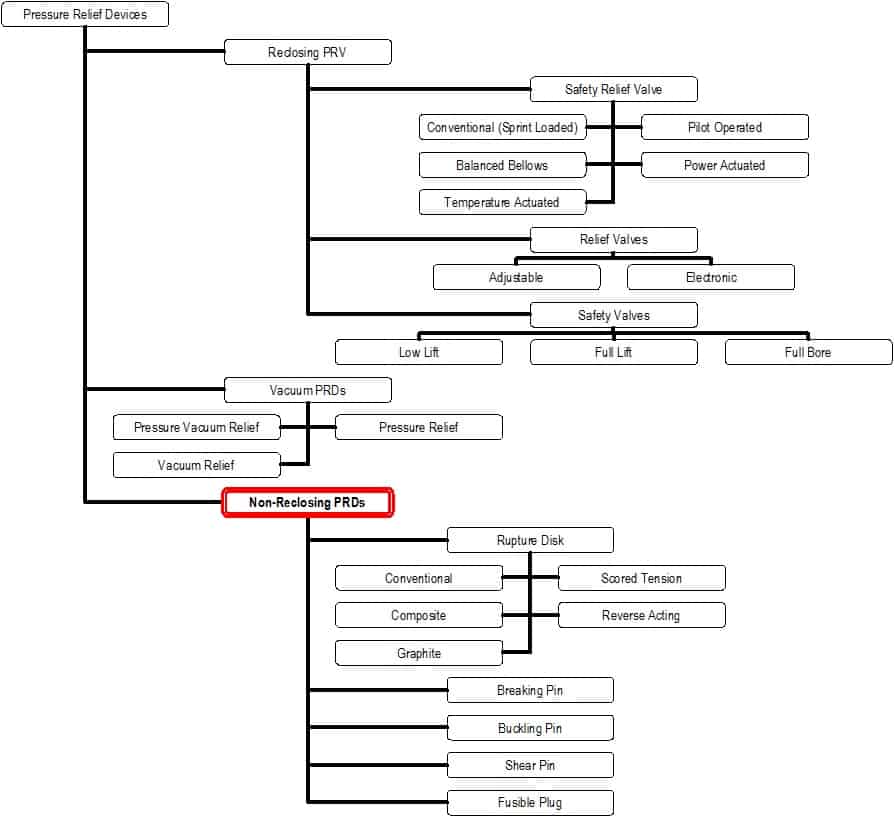
Pressure relief devices can be broken down into three broad categories often referred to as ‘reclosing pressure relief valves (PRV)’, ‘Vacuum pressure relief devices (vPRDs)’ and ‘non-reclosing pressure relief devices (PRDs)’, this article will explore the differences between these types and further investigate in detail the different subsets of non-reclosing devices. A diagram of many of these different devices and valves can be found in figure 1, with non-reclosing PRDs highlighted.
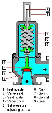
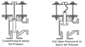
PRVs represent the largest portion of the market and can be found in everything from residential water heaters to nuclear submarines. They typically have their outlet rotated 90 degrees from their inlet and are held closed by a spring. Once the pressure on the upstream side reaches the set pressure the spring begins to compress and fluid is allowed to pass by. As the pressure grows the spring compresses more and the flow rate increases. Once the pressure is relieved the spring extends and recloses the valve, making it ready for another upset condition. Figure 2 shows a typical view of a PRV. These devices are typically governed by ASME VIII and compliance with that code is indicated by a ‘UV’ stamp on the device.
vPRDs represent a relatively niche market where components are protected from an internal vacuum forming. These devices will be ‘triggered’ when the internal pressure of the vessel the device is attached to reaches a specified pressure below atmospheric.
Non-reclosing pressure relief devices are recognized as a fundamentally different type of device than the more typical PRVs by ASME with the devices receiving a ‘UD’ stamp to confirm compliance with ASME VIII rather than a ‘UV’ stamp. The primary differentiating feature between a PRD and a PRV is that once triggered a PRD requires human input to replace the failed component that allowed the device to open. The failed component and method of failure varies across devices. Below are some examples of devices that fall under the non-reclosing device umbrella.
Rupture discs. This is the most prominent pressure relief device out there and what most people think about when they hear the term non-reclosing pressure relief device. In fact, much of the ASME VIII requirements appear to be written specifically with pressure relief devices in mind; the wider performance requirements, the assumed scalability of design and disc labeling requirements. Rupture discs have been around for many decades and will continue to be due to their simple design and inexpensive cost. Figure 3 shows some examples of rupture discs.

Disadvantages of rupture disc range from inconvenience to inaccuracy. Changing a rupture disc after it has been triggered requires the user to shut down the line in the area of the disc and open up the piping to remove the ruptured disc and replace it with a new disc. This can often be very costly and sometimes introduces un-necessary risks to the user. Rupture discs also have a tendency to lose strength over time due to fatigue effects from the process pressure constantly going up and down. This has been known to cause rupture discs to pop up to 30% below actual set pressure in the field. The ASME code allows UD certified PRDs in general to have a much wider berth in tolerances (+/- 2psi below 40 and +/- 5% over 40psi) compared to UV certified PRVs (+/- 2psi below 70 and +/- 3% over 70psi).
90o Buckling Pin. A very popular alternative to both rupture discs and ‘UV’ certified PRVs, the buckling pin device works similarly to a spring loaded PRV but has the spring replaced with a pin. Upon reaching the desired set pressure the pin buckles and allows to the device to open to full capacity. This is different than a spring loaded PRV due to the immediate opening behavior. It is very typical that a 90 degree buckling pin device will remain closed at 98% of set pressure and upon reaching 100% of set pressure it will open fully. There are many applications where this discrete behavior is highly advantageous. Figure 4 shows a diagram of a typical buckling pin device.
Disadvantages of a device such as this are after each upset condition the device will not reclose by itself due to plastic deformation of the pin during the buckling. These devices must be manually reset in the field by the user replacing the buckled pin with a new one. It is this permanent failure of the pin that causes these devices to be classified as a PRD and certified with the less strict UD stamp from ASME. The pin is equivalent to the disc in the original PRD rupture discs, of course the buckling pin is typically much cheaper than the replacing a disc due to both cost of the component and ease of replacement – you often do not have to open up the pipeline.
Inline Buckling Pin. There are many applications that require the immediate and discrete operation of the rupture disc and are too large in diameter to economically use the 90o buckling pin PRD. For these applications, an inline buckling pin has been developed. Rather than using a body and seal similar to a spring loaded PRV the inline buckling pin device utilizes the body and seal style of a typical butterfly control valve. This allows for an economic solution to large diameter pressure relief needs that require immediate full flow capacity once set pressure is reached.
Like all non-reclosing devices, the inline buckling pin device is also required to be manually reset once the pin fails. There are also additional costs associated with using an inline platform versus a 90o one in that the rotational motion of the shaft much be mechanically translated into linear motion required to actually buckle the pin. This translation of motion often requires additional components and mechanisms to be installed on the device and introduces additional points of failure.
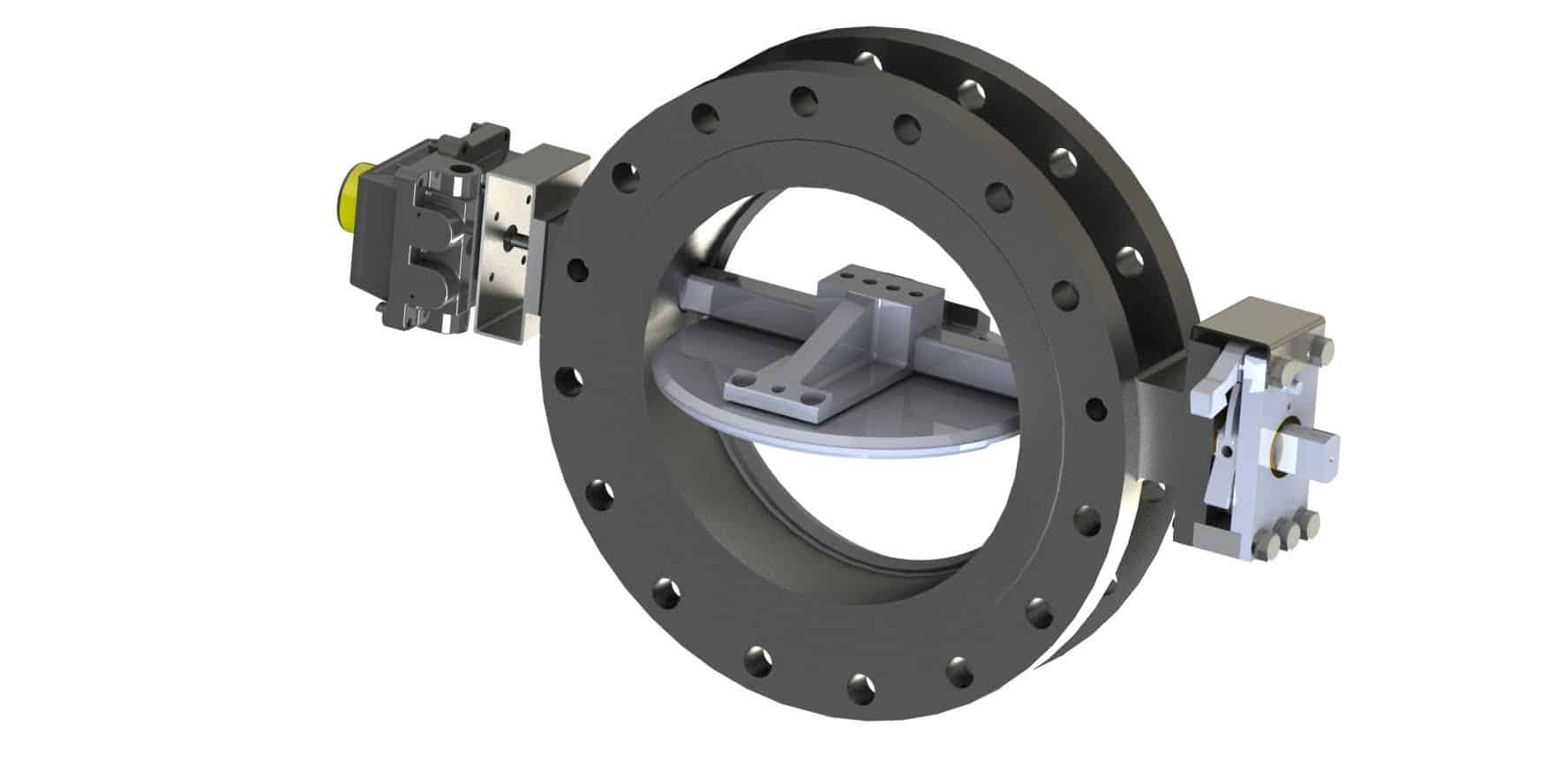
Inline Shear Pin. To address the disadvantages of and limitations of an inline buckling pin devices the inline shear pin device was developed. When the mechanisms required to buckle the pin via a rotation shaft provide too many possible points of failure the simpler and direct method of shearing a pin is a much simpler solution. Due to the failure mechanism of the pin this is often achieved with the use of no moving parts beyond the shaft providing a robust and direct mechanism for opening the device per figure 5.
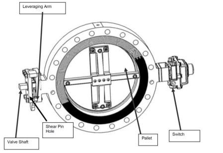
An additional advantage of the inline shear pin device is its ability to utilize the latest sealing technology found the control butterfly valve market; triple offset seals. Where inline buckling pin devices typically utilize the non-metallic seal/seat trims typical of double offset butterfly valves an inline shear pin device can use the lower friction laminated metals seals of the triple offset butterfly valves. This type of seal/seat combination can withstand both cryogenic temperatures and are also inherently fire safe.
The future of pressure relief devices will certainly include new and exciting technologies that work to solve the problems of today’s industrial companies. Figure 6 shows a view of an Accu-Shear inline shear pin device.
For more information on Accu-Shear please contact EnviroValve today info@envirovalve.net.